
Critical Considerations for Selecting Automotive RJ45 Interfaces: Balancing Water Resistance, EMI Immunity, and Data Rate
2025-06-19
Core Challenges in Automotive RJ45 Interface Selection
With the rapid adoption of in-vehicle Ethernet technology, automotive RJ45 interfaces, as key physical layer components connecting automotive network nodes, directly impact the reliability of core functions such as smart cockpits and ADAS (Advanced Driver Assistance Systems). Unlike consumer electronics, automotive environments present demanding operating conditions: temperature cycling from -40°C to 125°C, mechanical stress from constant vibration, and complex electromagnetic interference (EMI) generated by components such as engine ignition systems and radar modules. Therefore, three core technical indicators must be prioritized when selecting an interface: waterproof performance (to meet high-pressure washdown and water-crossing requirements), EMI immunity (to meet automotive EMC standards), and data transmission speed (to support high-speed data requirements). Based on international standards and OEM test data, this article analyzes the technical implications of these three indicators and discusses collaborative optimization strategies, providing a scientific basis for engineers and procurement personnel.
Water Resistance Performance: Technical Essentials from IP Rating to Structural Design
1. Analysis of Waterproof Rating Standards for In-Vehicle Environments
Automotive electronic waterproofing adheres to the ISO 20653 international standard. The core IP rating system defines IP67 as resistance to 30-minute immersion in 1m water depth, suitable for relatively dry areas like the cockpit and cabin. IP68, however, enables long-term underwater operation (e.g., engine compartment high-pressure washing or chassis wading scenarios), with specific immersion duration and depth customized by automakers (typically 24 hours at 2m depth). Testing by a German automaker revealed that non-compliant IP66-rated interfaces experienced a 15% water ingress failure rate after 20 high-pressure washes, highlighting that installation locations (engine compartment, chassis, cockpit) directly determine the required waterproof rating.
2. Key Elements of Waterproof Design
- Sealing Material Selection: Materials must balance temperature resistance and chemical stability. Fluororubber (FKM) seals are recommended for engine compartments, offering oil resistance and long-term operation at 150°C. In cold-region applications, silicone rubber (VMQ) is preferred for chassis interfaces, maintaining elasticity at -50°C.
- Structural Optimization: A "double-sealing" scheme combines a primary seal at the plug-socket contact surface with a cable waterproof boot at the tail, blocking water ingress paths. For example, an electric vehicle camera's automotive RJ45 connector reduces vibration-induced water risk by 60% through a snap-fit seal and cable locking structure.
3. Case Study of Typical Failure
A US automaker's after-sales data showed that a trunk-mounted automotive RJ45 network interface without tail waterproofing caused reversing camera glitches during rainy days. Disassembly revealed oxidation of metal contacts due to moisture ingress at the cable-socket junction, increasing contact resistance and causing signal interruptions. This issue led to a $390 per-vehicle repair cost and a 50,000-vehicle recall, underscoring the critical role of waterproof design in vehicle reliability.

EMI Immunity: EMC Design for In-Vehicle Electromagnetic Environments
1. Primary Sources of In-Vehicle Electromagnetic Interference (EMI)
In-vehicle EMI comprises two types: conducted interference from high-frequency noise (10kHz–1GHz) generated by engine IGBT modules and motor controllers, propagating through power and signal lines; and radiated interference from wireless devices like radar and 5G T-BOX, operating in the 80MHz–6GHz frequency range. Testing by a Chinese automaker showed that unshielded interfaces experienced a BER (Bit Error Rate) surge from 10⁻¹³ to 10⁻⁸ during full-engine load, severely impacting ADAS data transmission.
2. EMI Mitigation Techniques
- Hardware Shielding Design: Zinc-nickel alloy metal enclosures (shielding effectiveness ≥60dB@1GHz) with conductive anodizing meet IATF 16949 requirements. Paired with twisted-pair differential transmission (twist pitch ≤13mm), common-mode noise rejection improves by 40%.
- Grounding & Filtering Design: Multi-point grounding via metal spring contacts (ground impedance <50mΩ) minimizes ground loop interference. TDK BLM series common-mode chokes attenuate 10MHz–100MHz noise by over 30dB with <2dB insertion loss, balancing EMI immunity and transmission efficiency.
3. EMC Testing Standards & Certification
Products must pass CISPR 25 Class 5 testing, with key metrics: radiated emissions ≤40dBμV/m (30MHz–1GHz) and conducted emissions ≤70dBμV (150kHz–30MHz). A Japanese supplier’s delayed Complete vehicle EMC certification by 3 months due to insufficient shielding efficiency illustrates that EMI design is a mandatory supply chain entry criterion.

Data Transmission Rate: From Physical Layer Protocols to Signal Integrity Design
1. In-Vehicle Ethernet Rate Standards & Applications
With explosive growth in in-vehicle data (L2+ vehicles exceed 2Gbps per lane), automotive RJ45 interfaces must support multiple physical layer protocols:
|
Protocol Standard
|
Data Rate
|
Typical Applications
|
Maximum Cable Length
|
|
100BASE-T1
|
100Mbps
|
Body control, infotainment systems
|
≤15m
|
|
1000BASE-T1
|
1Gbps
|
ADAS sensors, domain controllers
|
≤15m
|
|
2.5GBASE-T1
|
2.5Gbps
|
8MP cameras, lidar data transmission
|
≤10m (under development)
|
2. Key Signal Integrity Parameters
- Return Loss (RL): Requirement ≤-20dB@100MHz demands control of contact impedance (<50mΩ) and cable characteristic impedance (100±10Ω). A Chinese connector manufacturer achieves 15% RL improvement via gold-plated terminals, reducing contact impedance to 35mΩ.
- Delay Skew: Inter-pair delay difference <5ns/m prevents inter-symbol interference (ISI) and BER degradation. At 1Gbps, each 1ns/m skew increase raises BER from 10⁻¹² to 10⁻¹⁰, compromising ADAS sensor synchronization accuracy.
3. Challenges in High-Speed Design
High-temperature environments (>85°C) alter cable dielectric constants, necessitating PTFE-insulated cables (dissipation factor <0.002). In dense installations, interface spacing ≥2x cable diameter or metal partitions are required to limit crosstalk below -35dB, ensuring data integrity for high-speed devices like lidar.

Balancing Strategies: Application-Based Selection Decision Model
1. Priority Mapping of Scenario-Based Requirements
Installation locations dictate varying emphasis on the three core specifications:
|
Installation Location
|
Water Resistance
|
EMI Immunity
|
Data Rate
|
Typical Applications
|
|
Engine Compartment
|
★★★★☆
|
★★★☆☆
|
★★☆☆☆
|
ECU, engine sensors
|
|
Cockpit
|
★★☆☆☆
|
★★★★☆
|
★★★★☆
|
Central computing platforms, smart cockpits
|
|
Chassis
|
★★★★★
|
★★★☆☆
|
★★☆☆☆
|
Wheel speed sensors, suspension control
|
|
Roof
|
★★★☆☆
|
★★☆☆☆
|
★★★★★
|
Lidar, high-precision positioning antennas
|
2. Trade-off Solutions for Technical Parameters
- High-Water Resistance Scenarios (e.g., chassis sensors): Select IP68-rated automotive RJ45 connectors with plastic shielded enclosures (20% cost reduction), supporting 100BASE-T1 to balance reliability and cost while meeting IPX9K high-pressure spray tests.
- High-Speed Scenarios (e.g., domain controllers): Deploy IP67 metal-shielded interfaces integrated with NXP TJA1145 transformer modules, supporting 1000BASE-T1 and Class 5 EMC certification to meet strict signal integrity requirements for L3+ autonomy.
- Cost-Sensitive Scenarios (e.g., body control modules): Use unshielded (UTP) interfaces with PCB-level LC filter circuits, sacrificing 10% EMI performance to achieve <$0.70 per-interface cost, suitable for low-speed body networks.
3. Supplier Selection Recommendations
Prioritize IATF 16949-certified suppliers:
- Premium Brands: TE Connectivity and Molex offer customized waterproof solutions for high-end vehicles.
- Cost-Effective Options: Luxshare and AVIC provide products passing 1000-hour salt spray tests and 20G vibration tests, with complete eye diagram reports (signal rise time <0.5ns).
Conclusion: Systematic Selection for Reliable In-Vehicle Networks
Selecting an automotive RJ45 interface requires more than optimizing individual specifications; it also requires systematic consideration of the installation environment, functional requirements, and cost constraints. OEMs and component manufacturers should adopt a three-dimensional evaluation framework: first, clearly prioritize specific scenarios (for example, autonomous driving prioritizes data rate and EMI, while body control prioritizes waterproofing); second, validate supplier solutions through vehicle-level EMC and thermal cycling testing; and finally, allow a 10%-20% performance margin (for example, the design temperature should be +20°C above the expected maximum operating temperature). By scientifically balancing waterproofing, EMI immunity, and data rate, stakeholders can effectively mitigate the risk of contact failures and signal distortion, laying a solid foundation for the reliability architecture of smart cars.
Aerospace RJ45 Connectors: Unveiling Six Core Advantages as the 'Lifeblood' of Aerospace Equipment
10 Core Advantages of Smart Grid RJ45 Connectors: High-Speed Transmission & EMI Resistance
Related Article

LAN Transformer vs Discrete Magnetics Guide | JIAXUN
LAN Transformer vs. Discrete Magnetics: Why Integrated RJ45 Connectors are Better for Modern Networking

Invitation | Jiaxun (Huizhou) Intelligent Technology Invites You to the 2026 Global Sources Consumer Electronics Show
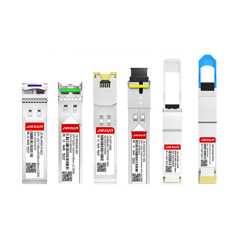
As global data traffic continues to grow rapidly, modern networks require faster and more efficient data transmission technologies. Optical transceivers play a critical role in fiber optic communication systems by converting electrical signals into optical signals for high-speed data transmission.
Complete Guide to SFP Modules and Optical Transceivers SFP, 10G SFP+, SFP28, QSFP28, QSFP-DD, 400G and 800G Modules Explained