Pinout for RJ45 Connector & How to Select the Right RJ45 Jack — JIAXUN Factory Technical Guide
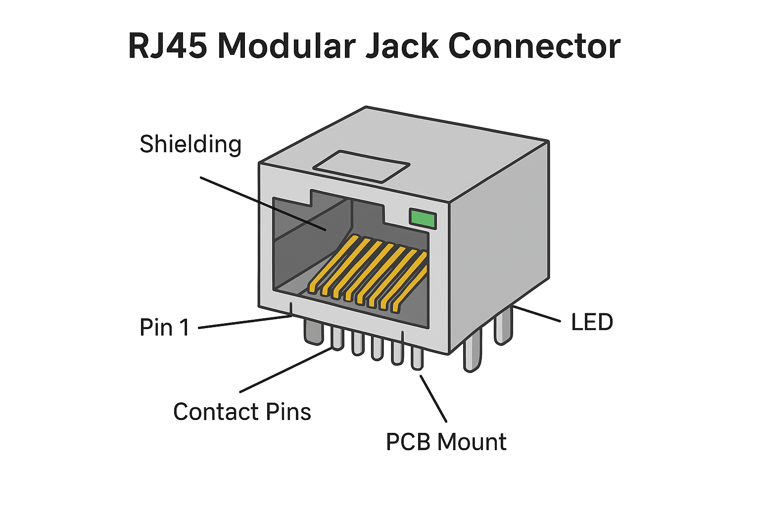
RJ45 connectors are fundamental components in Ethernet networking, PCB design, ICT infrastructure, and structured cabling. Whether you are a network engineer, hardware designer, or procurement specialist, understanding the pinout for an RJ45 connector is essential for ensuring signal integrity, compatibility, and long-term reliability of your application.
This complete technical guide explains the detailed pin mapping, signal definitions, Ethernet speed pin usage, PoE power distribution, and cable wiring standards.
Additionally, you will learn how to choose the correct RJ45 jack based on shielding type, PCB mounting format, PoE level, and performance categories — with professional engineering and manufacturing insight from JIAXUN, a leading RJ45 connector factory.
H2: 1. What Is an RJ45 Connector? (Quick Technical Overview)
The RJ45 connector is an 8-position, 8-contact (8P8C) modular connector standardized for Ethernet and structured cabling. It serves as both a physical interface and signal transmission medium for twisted-pair cables and PCB-mounted jacks.
H3: 1.1 Application Scenarios of RJ45 Connectors
RJ45 connectors are widely used in:
-
Ethernet networking equipment (switches, routers, gateways)
-
Industrial control networks
-
VoIP phones
-
PoE-powered devices (IP cameras, APs, POS terminals)
-
Telecom equipment
-
Smart home devices
-
Embedded systems and PCBs
-
Ethernet-based automation modules
H3: 1.2 Structure of an RJ45 Connector
Typical RJ45 plug or jack includes:
-
Housing — typically PC or nylon material
-
Contacts/Pins — phosphor bronze with gold plating
-
Shielding shell (optional) — conductive metal for EMI protection
-
Latch — for locking into socket
-
PCB pin or plug blades — depending on the type
H3: 1.3 Types of RJ45 Connectors
-
UTP (Unshielded)
-
STP/FTP (Shielded)
-
Cat5e, Cat6, Cat6A, Cat7 compatible RJ45
-
90° or 180° PCB mount modular jacks
-
With or without integrated magnetics (MagJack)
-
Single-port, multi-port, stacked types
H2: 2. Complete Pinout for RJ45 Connector (Pin 1–8 Detailed Explanation)
The RJ45 connector uses 8 pins, supporting differential pairs for Ethernet communication.
Below are the two wiring standards:
H3: 2.1 Standard TIA/EIA T568A Pinout
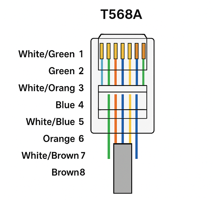
【Figure 1: T568A Color Code Diagram】
| Pin | Wire Color | Signal |
|---|---|---|
| 1 | White/Green | TX+ |
| 2 | Green | TX– |
| 3 | White/Orange | RX+ |
| 4 | Blue | — |
| 5 | White/Blue | — |
| 6 | Orange | RX– |
| 7 | White/Brown | — |
| 8 | Brown | — |
H3: 2.2 Standard TIA/EIA T568B Pinout (Most Common Worldwide)
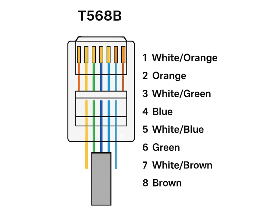
【Figure 2: T568B Color Code Diagram】
| Pin | Wire Color | Signal |
|---|---|---|
| 1 | White/Orange | TX+ |
| 2 | Orange | TX– |
| 3 | White/Green | RX+ |
| 4 | Blue | — |
| 5 | White/Blue | — |
| 6 | Green | RX– |
| 7 | White/Brown | — |
| 8 | Brown | — |
H3: 2.3 T568A vs T568B Differences
Only two pairs are swapped:
-
Green ↔ Orange pairs
-
Both standards use the same electrical performance
-
T568B is widely used in commercial networks
-
T568A is more common in government/US residential networks
H3: 2.4 Pin Function Definitions for Ethernet (TX/RX Signals)
Ethernet uses differential signaling, meaning each signal transmits across a twisted pair:
-
TX+ / TX– — transmit differential pair
-
RX+ / RX– — receive differential pair
-
Unused pins — used by Gigabit Ethernet or PoE
H3: 2.5 Signal Pairing Principle
Twisted pairs must remain in pairs to avoid:
-
Crosstalk (NEXT/FEXT)
-
Signal degradation
-
Impedance mismatch

【Figure 3: Differential Pairing Structure】
H4: T568A & T568B Pinout Table (Side-by-Side Comparison)

【Figure 4: T568A vs T568B Comparison Table】
H2: 3. Pinout for Different Ethernet Standards (10/100/1000/10G)
Different Ethernet speeds use different pin combinations.
H3: 3.1 10/100 Mbps Ethernet Pinout
Uses two differential pairs:
-
Pair 2 → Pins 1 & 2 (TX)
-
Pair 3 → Pins 3 & 6 (RX)

【Figure 5: 10/100BASE-T Wiring Map】
H3: 3.2 Gigabit Ethernet (1000BASE-T)
Uses all four pairs, meaning all 8 pins are active.
| Pair | Pins | Function |
|---|---|---|
| Pair 1 | 1–2 | Bi-directional data |
| Pair 2 | 3–6 | Bi-directional data |
| Pair 3 | 4–5 | Bi-directional data |
| Pair 4 | 7–8 | Bi-directional data |
H3: 3.3 10GBASE-T (10 Gigabit Ethernet)
Key requirements:
-
Fully shielded cable recommended
-
All pairs active
-
Requires Cat6A or above
-
Supports up to 100 meters
H4: Comparison Table: Ethernet Speed vs Pin Usage

【Figure 6: Ethernet Speed vs Pin Assignment Table】
H2: 4. Pinout for PoE (Power over Ethernet) Standards
PoE injects power through the same twisted pairs used for data transmission.
H3: 4.1 PoE / PoE+ (802.3af / 802.3at)
Provides:
-
15.4W (PoE)
-
30W (PoE+)
H3: 4.2 PoE++ (802.3bt Type 3/4)
Provides:
-
60W (Type 3)
-
90–100W (Type 4)
Used in:
-
HD PTZ cameras
-
Access Points
-
POS systems
-
LED lighting
H3: 4.3 Mode A & Mode B Pin Mapping
| Mode | Pins with Power |
|---|---|
| Mode A | 1–2 and 3–6 |
| Mode B | 4–5 and 7–8 |
| 802.3bt | all 4 pairs |
H4: PoE Pin Mapping Table

【Figure 7: PoE Modes A/B Pinout Diagram】
H2: 5. Straight-Through vs Crossover Pinout
H3: 5.1 Straight-Through Cable Pinout
Used for:
-
PC → Switch
-
Router → Switch
-
General LAN cabling
【Figure 8: Straight-Through Cable Diagram】
H3: 5.2 Crossover Cable Pinout
Crosses TX and RX pairs:
| One End | Other End |
|---|---|
| T568A | T568B |
Used for:
-
PC ↔ PC
-
Switch ↔ Switch
-
Router ↔ Router
Modern Gigabit Ethernet auto-detects crossover automatically (Auto-MDI/MDIX).
H3: 5.3 When to Use Each
-
Straight-through: 99% of modern networks
-
Crossover: Legacy hardware only
H2: 6. How to Choose the Right RJ45 Connector for Your Application
Selecting an appropriate RJ45 connector ensures performance, longevity, and compatibility.
H3: 6.1 Choose by Category
| Category | Bandwidth | Recommended Application |
|---|---|---|
| Cat5e | 100 MHz | Basic networking |
| Cat6 | 250 MHz | Gigabit Ethernet |
| Cat6A | 500 MHz | 10G Ethernet |
| Cat7 | 600+ MHz | EMI-critical systems |
H3: 6.2 Shielded vs Unshielded
-
STP/FTP — industrial, automotive, PoE++
-
UTP — office, home networks
【Figure 9: Shielded vs Unshielded RJ45 Comparison】
H3: 6.3 Connector Form Factor: 90°, 180°, 8P8C
-
90° modular jack — vertical PCB mount
-
180° modular jack — horizontal PCB mount
-
Plug types — field termination, crimp types
H3: 6.4 PCB Mount Types
-
Through-Hole (THT) — stronger mechanical support
-
SMT — compact consumer electronics
-
Magnetics Integrated — networking equipment
H3: 6.5 RJ45 for PoE Applications
Look for:
-
High-current pins
-
Lower contact resistance
-
50µ" gold plating
-
Heat-resistant housing
-
Anti-warping design
H4: Supplier Evaluation Checklist
-
ISO9001 factory?
-
Automated production lines?
-
Gold plating thickness verification?
-
Shielding effectiveness test?
-
100% electrical continuity test?
H2: 7. JIAXUN: Professional RJ45 Connector Manufacturer & Factory Capabilities
As a leading OEM/ODM manufacturer, JIAXUN provides high-performance RJ45 connectors for global networking brands.
H3: 7.1 About JIAXUN
-
Located in Guangdong, China
-
10,000+ m² factory
-
20+ years of RJ45 connector manufacturing
-
Exported to 80+ countries
H3: 7.2 Automated Production Lines
JIAXUN factory uses:
-
Automatic pin insertion machines
-
High-speed SMT lines
-
Shielding forming + riveting automation
-
Automated optical & electrical testing systems
These ensure consistency, reliability, and 0.03% defect rate.
H3: 7.3 Strong OEM/ODM Customization Ability
-
Custom pinout
-
Private-label modular jacks
-
Custom magnetics
-
High-temp or industrial-grade materials
-
Multi-port stacked designs
H3: 7.4 Full Product Range
-
RJ45 modular jacks (THT/SMT)
-
Shielded RJ45 connectors
-
Integrated RJ45 magnetics
-
Cat6/Cat6A shielded jacks
-
PoE++ (802.3bt) RJ45 connectors
H3: 7.5 Quality Certifications
-
ISO9001
-
UL
-
RoHS
-
REACH
-
Strict 100% pin continuity testing
H4: Why Global Brands Choose JIAXUN
-
High reliability
-
Stable global supply chain
-
Competitive pricing
-
Professional engineering support
-
Strong customization capability
H2: 8. Common Mistakes When Understanding RJ45 Pinout
H3: 8.1 Mixing T568A and T568B
Leads to mismatched cable wiring.
H3: 8.2 Untwisting Pairs Too Much
Causes signal loss and crosstalk.
H3: 8.3 Using Wrong Category Connector
Cat5e plug on Cat6 cable = performance drop.
H3: 8.4 Using Non-PoE Connectors for PoE++
Leads to overheating and failure.H2: 9. Conclusion
Understanding the correct pinout for RJ45 connectors is essential for designing, installing, and maintaining reliable Ethernet networks. With different wiring standards, PoE configurations, and speed requirements, engineers must carefully select the appropriate RJ45 connector type.
As a professional manufacturer, JIAXUN provides industry-grade RJ45 connectors with strong OEM/ODM customization, high durability, and compliance with global standards — making it a trusted partner for networking equipment brands worldwide.
RJ45 Connector Diagram: Pinout, Wiring (T568A/B), Structure & OEM Guide — Powered by JIAXUN
What Is an RJ45 Connector? Complete Guide to RJ45 Pinout, Types, Wiring, and Applications
Related Article