
pinout for rj45 connector
2025-07-07

The pinout for rj45 connector follows standardized physical layouts and two mainstream wiring standards (T568A and T568B). Here is a detailed explanation:

1. Pin Numbering Rules
When the RJ45 plug is facing upward (i.e., the gold-plated contacts are up, and the tab is down), the pins are numbered 1 to 8 from left to right. This numbering method is industry-standard; the pin positions remain fixed regardless of the wiring standard used.
2. T568A vs. T568B Wiring Standards
The core difference between the two standards lies in the swapped positions of the orange and green wire pairs, while other pairs (blue, brown) remain unchanged:
-
T568A Wiring (commonly used in government or international projects):
- Green-White
- Green
- Orange-White
- Blue
- Blue-White
- Orange
- Brown-White
- Brown
-
T568B Wiring (predominant in North America, most widely used):
- Orange-White
- Orange
- Green-White
- Blue
- Blue-White
- Green
- Brown-White
- Brown
Both standards perform identically; the key is to maintain consistency within the same network. For example, if one end uses T568B, the other end must also use T568B (straight-through cable); if the two ends use T568A and T568B respectively, it becomes a crossover cable, used to connect similar devices (e.g., two computers).

3. Pin Function Definitions
In common 10/100Base-T Ethernet, only 4 pins are used:
- Transmit Data (TX): Pin 1 (TX+), Pin 2 (TX-)
- Receive Data (RX): Pin 3 (RX+), Pin 6 (RX-)
- Unused: Pins 4, 5, 7, and 8 are typically left idle.
In Gigabit Ethernet (1000Base-T), all 8 pins are utilized, enabling higher bandwidth through full-duplex communication. Here, pins 1-2, 3-6, 4-5, and 7-8 form four pairs of differential signals for bidirectional data transmission.
4. Physical Arrangement & Manufacturing Tips
- Plug Orientation: Ensure the plug faces upward (tab down), with pins arranged left to right in order.
- Pair Twisting: Maintain the twisted state of wire pairs close to the plug to reduce signal interference. For example, pairs like orange-white-orange and green-white-green should remain tightly twisted.
- Consistency: For straight-through cables, both ends must follow the same standard; for crossover cables, one end uses T568A and the other uses T568B.
5. Application Examples
- Straight-through Cable: Connects different types of devices (e.g., computer to switch), with both ends using T568B.
- Crossover Cable: Connects similar devices (e.g., computer to computer), with one end using T568A and the other using T568B.
By following these rules, proper wiring of RJ45 connectors can be ensured, avoiding communication failures caused by incorrect wiring. In practice, it is recommended to use standard tools (e.g., cable testers) to verify compliance with expectations.
RJ45 Connector Pinout
Exploring the Latest LAN Transformer Solutions for Efficient Power Distribution
Related Article

LAN Transformer vs Discrete Magnetics Guide | JIAXUN
LAN Transformer vs. Discrete Magnetics: Why Integrated RJ45 Connectors are Better for Modern Networking


Invitation | Jiaxun (Huizhou) Intelligent Technology Invites You to the 2026 Global Sources Consumer Electronics Show
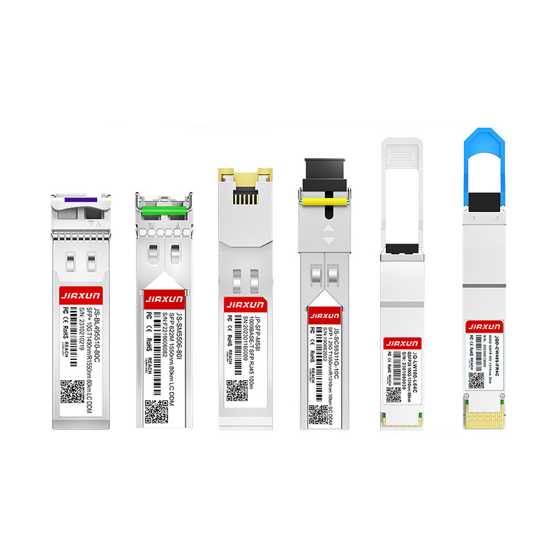
As global data traffic continues to grow rapidly, modern networks require faster and more efficient data transmission technologies. Optical transceivers play a critical role in fiber optic communication systems by converting electrical signals into optical signals for high-speed data transmission.
Complete Guide to SFP Modules and Optical Transceivers SFP, 10G SFP+, SFP28, QSFP28, QSFP-DD, 400G and 800G Modules Explained