
RJ45 Connector Pinout
2025-07-07

The pin arrangement of an RJ45 female connector follows the T568A or T568B standards, with the specific sequence depending on the application scenario. Here is a detailed explanation:

Pin Arrangement Rules
-
Viewing Angle:
When viewed from the front of the female connector (the direction the plug is inserted), with the tab facing down and the metal contacts facing you, the leftmost pin is Pin 1, and the rightmost is Pin 8. -
T568A Standard:
- Pin 1: White-green (Receive Data Positive RX+)
- Pin 2: Green (Receive Data Negative RX-)
- Pin 3: White-orange (Transmit Data Positive TX+)
- Pin 4: Blue (Unused / Gigabit bidirectional data +)
- Pin 5: White-blue (Unused / Gigabit bidirectional data -)
- Pin 6: Orange (Transmit Data Negative TX-)
- Pin 7: White-brown (Unused / Gigabit bidirectional data +)
- Pin 8: Brown (Unused / Gigabit bidirectional data -)
Mnemonic: Green, blue, orange, brown; light colors first, swap pins 3 and 5.
-
T568B Standard:
- Pin 1: White-orange (Transmit Data Positive TX+)
- Pin 2: Orange (Transmit Data Negative TX-)
- Pin 3: White-green (Receive Data Positive RX+)
- Pin 4: Blue (Unused / Gigabit bidirectional data +)
- Pin 5: White-blue (Unused / Gigabit bidirectional data -)
- Pin 6: Green (Receive Data Negative RX-)
- Pin 7: White-brown (Unused / Gigabit bidirectional data +)
- Pin 8: Brown (Unused / Gigabit bidirectional data -)
Mnemonic: Orange, blue, green, brown; light colors first, swap pins 3 and 5.

Key Features and Applications
-
Data Transmission:
- 10/100Base-T: Uses only pins 1, 2, 3, and 6 (two pairs of differential signals), with T568B being more common.
- Gigabit Ethernet (1000Base-T): Uses all 8 pins to enable bidirectional data transmission.
-
Crossover vs. Straight-Through Cables:
- Straight-through cable: Both ends use T568B or T568A, used to connect different devices (e.g., a computer and a switch).
- Crossover cable: One end uses T568B, the other T568A, used to connect similar devices (e.g., a computer to another computer).
-
PoE (Power over Ethernet):
- Mode A: Delivers power through pins 1, 2, 3, and 6 (data and power share the same pairs).
- Mode B: Delivers power through pins 4, 5, 7, and 8 (using idle pairs).
-
Pin Identification:
Female connectors typically have no additional markings; the direction is determined by the tab position (when the tab is facing down, the leftmost is Pin 1).
Notes
- Compatibility: T568A and T568B can be mixed, but ensure consistency between both ends or use a crossover cable.
- Special Designs: Some female connectors with network transformers may adjust pin functions, but the arrangement still follows the standards.
- Shielded vs. Unshielded: Shielded female connectors must be used with shielded cables; the pin arrangement remains unchanged.
Summary: The pin arrangement of RJ45 female connectors is based on T568A/B, with the specific choice depending on device types and application scenarios. Gigabit Ethernet and PoE expand pin functions, while the physical arrangement remains consistent. In practice, it is recommended to confirm the specific connection method according to device markings or standard wiring diagrams.
CE Certified RJ45 Interface: A Quality Choice for Network Connections, Empowering Efficient Business Expansion
pinout for rj45 connector
Related Article

LAN Transformer vs Discrete Magnetics Guide | JIAXUN
LAN Transformer vs. Discrete Magnetics: Why Integrated RJ45 Connectors are Better for Modern Networking

Invitation | Jiaxun (Huizhou) Intelligent Technology Invites You to the 2026 Global Sources Consumer Electronics Show
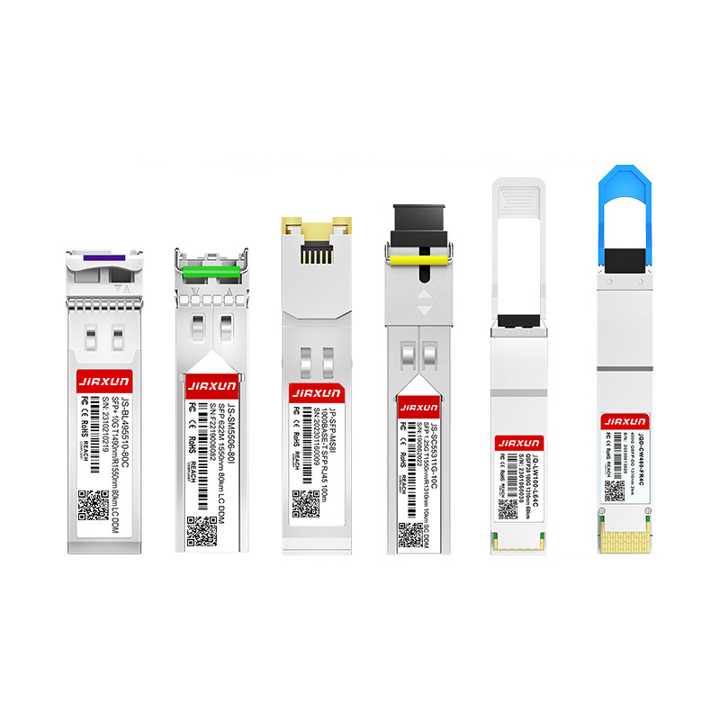
As global data traffic continues to grow rapidly, modern networks require faster and more efficient data transmission technologies. Optical transceivers play a critical role in fiber optic communication systems by converting electrical signals into optical signals for high-speed data transmission.
Complete Guide to SFP Modules and Optical Transceivers SFP, 10G SFP+, SFP28, QSFP28, QSFP-DD, 400G and 800G Modules Explained