
RJ45 Connector Wiring Diagram
2025-06-06

The RJ45 connector is the backbone of Ethernet networking, enabling reliable data transmission across wired networks. Understanding its wiring diagram and proper installation is crucial for ensuring stable connections. This article provides a comprehensive guide to RJ45 wiring, including standards, tools, and step-by-step instructions, accompanied by visual diagrams.
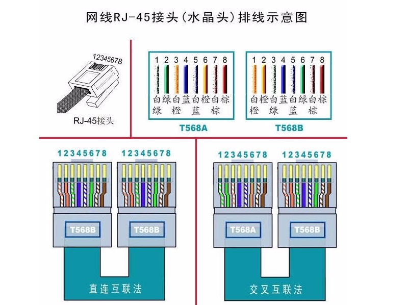
Understanding RJ45 Wiring Standards
The RJ45 connector uses 8P8C (8 Position 8 Contact) pins to interface with twisted-pair Ethernet cables. Two primary wiring standards exist: T568A and T568B . Both are widely accepted, but T568B is more commonly used in residential and commercial setups, especially in China .
T568A Wiring Sequence
- White/Green
- Green
- White/Orange
- Blue
- White/Blue
- Orange
- White/Brown
- Brown
T568B Wiring Sequence
- White/Orange
- Orange
- White/Green
- Blue
- White/Blue
- Green
- White/Brown
- Brown
The key difference lies in the swapping of the Green and Orange wire pairs. Both standards support 10/100/1000BASE-T Ethernet, but T568B offers better noise isolation .
Tools and Materials Required
To terminate an RJ45 connector, gather the following:
- RJ45 connectors (shielded or unshielded, depending on cable type).
- Twisted-pair Ethernet cable (Cat5e, Cat6, or Cat6a).
- RJ45 crimping tool (e.g., Greenlee 620, Klein Tools VDV-526-100) .
- Cable stripper (integrated into most crimping tools).
- Network cable tester (e.g., Fluke Networks DSP-4000) to verify connectivity .
Step-by-Step Wiring Guide
1. Prepare the Cable
- Cut the cable to the desired length using the crimping tool’s built-in cutter.
- Strip 2–3 cm of the outer sheath using the stripper, ensuring the inner wires remain intact .
- Remove the plastic separator between the wire pairs if present.
2. Untwist and Sort the Wires
- Untwist each wire pair and align them according to T568B or T568A standards.
- Ensure the wires lie flat and parallel, avoiding overlapping.
- Trim the wires to 12–14 mm from the sheath to ensure they fit snugly into the RJ45 connector .
3. Insert the Wires into the Connector
- Hold the RJ45 connector with the clip facing down and the metal pins facing up.
- Insert the sorted wires into the connector in the correct order, pushing them fully to the bottom of the housing.
- Ensure the sheath extends slightly into the connector for mechanical stability .
4. Crimp the Connector
- Place the RJ45 connector into the crimping tool’s slot, aligning it with the 8P8C die.
- Squeeze the tool firmly to crimp the pins into the wires, securing the connection.
- For shielded cables, ensure the metal shield is crimped into the connector’s strain relief .
5. Test the Connection
- Use a network tester to verify continuity. For a straight-through cable (both ends T568B), the tester should light up in sequence (1–8).
- For a cross-over cable (one end T568A, the other T568B), the tester will show a swapped pattern (1↔3, 2↔6) .
Common Wiring Mistakes to Avoid
- Incorrect Wire Order: Misaligning wires (e.g., swapping Green and Orange pairs) will disrupt data transmission.
- Excessive Stripping: Leaving too much wire exposed increases interference risk.
- Poor Crimping: Weak crimps lead to loose connections; ensure the tool fully compresses the pins .
- Using Low-Quality Tools: Inferior crimpers may damage connectors or wires.
- Ignoring Shielding: Shielded cables require proper grounding for optimal performance .
Advanced Considerations
- Cable Types: Cat5e supports up to 1 Gbps, while Cat6/Cat6a enables 10 Gbps over shorter/longer distances, respectively. Use compatible connectors for each .
- PoE (Power over Ethernet): Ensure connectors support PoE standards (e.g., IEEE 802.3af/at) if powering devices like IP cameras or VoIP phones .
- Troubleshooting: If connectivity fails, check LED indicators on network devices, test with a different cable, or use a TDR (Time Domain Reflectometer) to detect faults .
Conclusion
Mastering RJ45 wiring ensures reliable Ethernet connections for home, office, or industrial networks. By following the T568A/B standards, using quality tools, and avoiding common pitfalls, you can create durable cables that support high-speed data transmission. Always test your work with a network tester to guarantee performance. For advanced applications, consider cable shielding and PoE compatibility.
How Shielded RJ45 Connectors Protect Against EMI/RFI Interference
How to Install and Troubleshoot Ethernet Connector RJ45
Related Article

LAN Transformer vs Discrete Magnetics Guide | JIAXUN
LAN Transformer vs. Discrete Magnetics: Why Integrated RJ45 Connectors are Better for Modern Networking
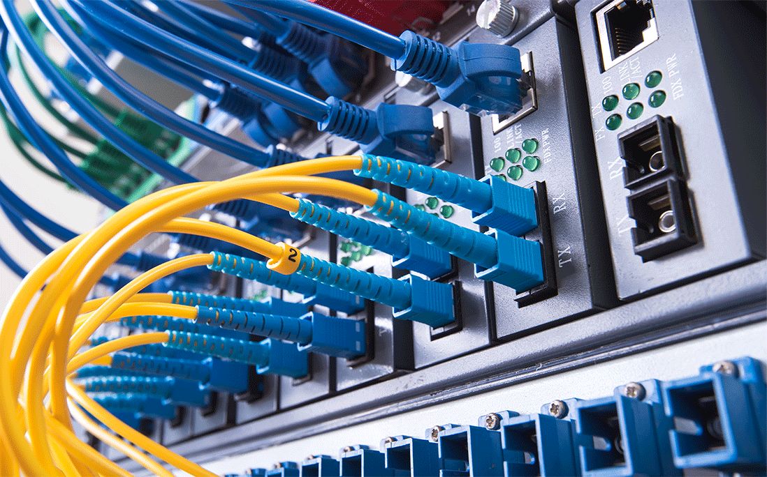

Invitation | Jiaxun (Huizhou) Intelligent Technology Invites You to the 2026 Global Sources Consumer Electronics Show
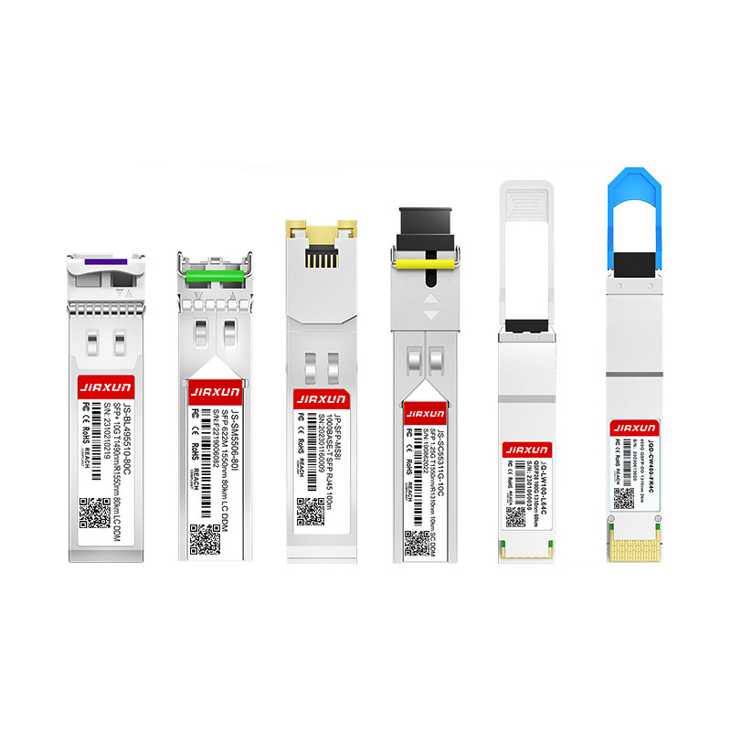
As global data traffic continues to grow rapidly, modern networks require faster and more efficient data transmission technologies. Optical transceivers play a critical role in fiber optic communication systems by converting electrical signals into optical signals for high-speed data transmission.
Complete Guide to SFP Modules and Optical Transceivers SFP, 10G SFP+, SFP28, QSFP28, QSFP-DD, 400G and 800G Modules Explained